Build a Self-Driving Car in Carla Simulator with Python (Step-by-Step)
Last Updated on August 26, 2025 by Editorial Team
Author(s):
Originally published on Towards AI.

Autonomous vehicles are becoming increasingly common on our roads. Waymo has already surpassed Lyft in total rides in San Francisco and is rapidly approaching Uber. Hundreds of sensor-equipped cars can now be spotted in cities like New York and Shanghai. What kind of magic makes these vehicles move by themselves?
In this article, we’ll explore the essential components of self-driving systems and build our autonomous car using Python within the Carla simulator (based on Unreal Engine 4). Initially, our vehicle won’t move, but by the end, it’ll follow a specified route and halt automatically in front of obstacles.
⭐ Star the repo → https://github.com/andrey7mel/carla-python-examples
Key components of a self-driving system
- Localization: Accurate determination of the car’s position, down to centimeters, achieved with sensors and highly detailed maps storing road markings, signs, and traffic lights. This ensures reliable navigation even when visible markings are obscured, like in winter conditions.
- Perception: Detection and tracking of surrounding objects, measuring their position, speed, and trajectory.
- Prediction: Anticipation of the movements and behaviors of other road users — arguably the most complex task due to human unpredictability.
- Planning: Decision-making based on gathered localization, perception, and prediction data, translating into actionable commands. These decisions happen rapidly — in milliseconds.
- Control: Execution of commands to directly maneuver the vehicle.

Carla Simulator
While we don’t have access to a physical vehicle equipped with advanced sensors, Carla, an open-source self-driving simulator, provides us with an ideal virtual environment. Higher Carla versions require increasingly powerful hardware; we’ll use Python 3.8 and Carla 0.9.15, with all the necessary code available on GitHub.
Installation Steps (Windows):
- Download Carla 0.9.1.5 (Windows), unpack it, and ensure the extracted folder contains “WindowsNoEditor”.
- Start
WindowsNoEditor/CarlaUE4.exeto explore the map via a flying camera. Remember to close it afterward, as it's resource-intensive. - Install Python 3.8 from the Windows Store
- Open PowerShell inside your Carla directory (CARLA_0.9.15), either by right-clicking inside the folder and selecting “Open in Terminal” or using Shift + Right-click to reveal this option.
- Set up your Python virtual environment (specifically with Python 3.8):
py -3.8 -m venv venv
venv\Scripts\activate
- Install dependencies:
pip3 install -r WindowsNoEditor\PythonAPI\examples\requirements.txt
pip3 install carla
- Launch Carla again (
WindowsNoEditor/CarlaUE4.exe) and run the manual control script:
python WindowsNoEditor\PythonAPI\examples\manual_control.py
- You’ll now be able to control your vehicle using the familiar WSAD keys
- Download the repository containing example code and extract it into:
WindowsNoEditor\PythonAPI\
so the folder structure looks like:
WindowsNoEditor\PythonAPI\carla-python-examples-main\sd_1,sd_2, etc. - Enter the examples directory:
cd WindowsNoEditor\PythonAPI\carla-python-examples-main
- Finally, verify the example by running:
python -m sd_1
The simulator camera should then automatically position itself above your car:

Creating Your First Autonomous Vehicle
Code on Github
Launch command: python -m sd_1
Let’s create our first autonomous vehicle:
# Connect to the Carla server
client = carla.Client('localhost', 2000)
client.set_timeout(10.0)
world = client.get_world()

# Remove the previous vehicle
remove_previous_vehicle(world)

# Spawn a new vehicle
spawn_point = world.get_map().get_spawn_points()[0]
vehicle_bp = world.get_blueprint_library().filter('vehicle.tesla.model3')[0]
vehicle_bp.set_attribute('role_name', 'my_car')
vehicle = world.try_spawn_actor(vehicle_bp, spawn_point)
We’ve created a vehicle, but the simulator doesn’t show any changes. This is due to Carla’s architecture: the simulator’s observer (spectator) doesn’t automatically detect vehicles spawned by clients. To resolve this, let’s attach the spectator’s camera to the car.
# Set the spectator camera
spectator = world.get_spectator()
transform = vehicle.get_transform()
forward_vector = transform.get_forward_vector()
offset = carla.Location(x=-20 * forward_vector.x, y=-20 * forward_vector.y, z=15)
spectator_transform = carla.Transform(transform.location + offset,
 carla.Rotation(pitch=-30, yaw=transform.rotation.yaw, roll=transform.rotation.roll))
spectator.set_transform(spectator_transform)
Now our autonomous vehicle is created and ready for its first ride!
Full Speed Ahead!
Code on Github
Launch command: python -m sd_2
First, we’ll teach our car to drive straight forward. The basic controls of a car with an automatic transmission include the throttle, brake, and steering. Carla simulator provides a special command called VehicleControl, sent to the car every simulation iteration. Simultaneously, we'll update the spectator camera’s position:
# Vehicle control
control = carla.VehicleControl()
control.steer = 0.0
control.throttle = 1.0
control.brake = 0.0
vehicle.apply_control(control)

# Update spectator position
spectator.set_transform(get_transform_for_spectator(vehicle.get_transform()))
Run this code and enjoy a straight and swift ride toward the nearest building! Congratulations — your self-driving car just completed its first meters autonomously!
In reality, what we’ve just done with a few lines of code is a highly challenging engineering task. A real-world implementation requires a modern vehicle with controllable core systems, reliable onboard computer communication, and stable equipment operation, preventing system freezes at high speeds.
Localization — Where Are We?
After creating the vehicle, we need to know its exact position.
Localization is the precise determination of the vehicle’s position with centimeter-level accuracy. Real-world autonomous vehicles rarely rely solely on GPS due to its limited precision. Instead, LiDAR-based mapping methods are preferred, enabling the vehicle to scan its surroundings in motion and match them against previously prepared high-resolution maps. This process ensures centimeter-level accuracy.
Localization data allows us to use detailed maps, containing road markings, traffic lights, and road signs. These maps help autonomous software handle challenging situations, such as snow-covered roads without visible lane markings.
In our simulator, we’ll assume a pre-implemented localization module already provides correct positioning data.
# Vehicle data retrieval function
# Example coordinates from the simulator's coordinate system:
# Location(x=65.516640, y=7.807766, z=0.038288)
def get_location(vehicle):
 return vehicle.get_location()
We can similarly obtain the car’s current speed. In the simulator, the velocity is directly accessible, whereas in real life, it is calculated by the onboard computer based on wheel and shaft rotations:
def get_speed(vehicle):
 """Returns the current speed of the vehicle in km/h."""
 velocity_vector = vehicle.get_velocity()
 # Compute the speed magnitude (in m/s)
 speed_meters_per_second = np.linalg.norm([velocity_vector.x, velocity_vector.y, velocity_vector.z])
 # Convert speed to km/h
 return 3.6 * speed_meters_per_second
In short: the Localization module provides the exact position, speed, acceleration, and heading by analyzing sensor input data.
Visualizing Data
Code on Github
Launch command: python -m sd_3
To analyze vehicle motion, we’ll create simple plots using matplotlib to visualize its current location and speed. For now, our car moves straight along the X-axis, so only the X coordinate changes.

We’ll also refine the spectator camera visualization. Constantly moving Carla’s built-in camera can cause jittering, so we’ll use pygame and a separate window for smoother observation:
pygame_display = PygameDisplay(world, vehicle)
pygame_display.render()
plotter = Plotter()
plotter.init_plot()
plotter.update_plot(current_sim_time_sec, current_location.x, current_speed_kmh, 0.0)
Let’s combine all parts and run:
python -m sd_3
Planning — Where and How to Go?
Code on Github
Launch command: python -m sd_4
After achieving the basic “drive straight forward” mode, let’s tackle a more challenging scenario — stopping at an intersection. For this, we’ll implement a Planning module. Planning typically comprises:
- Global Planning: Generates the overall route, much like a GPS navigator, guiding you through streets and intersections.
- Behavior Planning: Decides specific maneuvers (turn, go straight, yield, etc.), based on current position and objects detected by Perception.
- Local Planning (Trajectory Planning): Creates precise trajectories and speed profiles based on Behavior Planning’s decisions.

Waypoints
Waypoints are positions along the trajectory specifying the desired speed at each point, usually as coordinates x, y, and desired speed v (ignoring altitude z for now). Optionally, they may contain additional data, like heading and acceleration.
Here’s a simple waypoint example for approaching an intersection:
# Waypoints [x, y, desired_speed_kmh]
WAYPOINTS = [
 [-64, 24.5, 40], # Starting point (40 km/h)
 [40, 24.5, 40], # Cruising toward braking point (40 km/h)
 [70, 24.5, 0] # Stopping point (0 km/h)
]
Our goal is to achieve the specified speed at each waypoint. We’ll implement a waypoint check and switching logic (currently only considering the X-axis):
def update(vehicle_location_x, waypoints, target_waypoint_id):
 if abs(waypoints[target_waypoint_id][0] - vehicle_location_x) < 5 \
 and target_waypoint_id < len(waypoints) - 1:
 target_waypoint_id += 1
 return target_waypoint_id
In short: the Planning module selects optimal routes based on the current vehicle status (Localization) and surrounding environment (Perception), outputting waypoints with detailed parameters.
Control — Managing Speed and Steering
Once we’ve planned a trajectory and speed profile, we convert them into concrete throttle and brake commands using the Control module.
Here’s a basic two-stage speed controller:
if v_current < v_desired:
 control.throttle = 1.0 # Accelerate
 control.brake = 0.0
elif v_current > v_desired:
 control.throttle = 0.0 # Brake
 control.brake = 1.0
This maintains speed within the desired range. To enable a complete stop, we add:
if v_desired == 0:
 control.brake = 1.0 # Full stop
 control.throttle = 0.0
Launch and test:
python -m sd_4

Although this straightforward approach maintains roughly 40 km/h, abrupt throttle and brake inputs create discomfort. For smoother rides, we’ll explore a PID controller implementation in part two of this article.
PID Speed Controller
Code on Github
Launch command: python -m sd_5
A PID controller is among the most common automatic control systems, designed to smoothly maintain a target value (like vehicle speed) without harsh oscillations. It consists of three parts:
- Proportional (P): Depends directly on the current “error” — the difference between actual and desired speed. The larger the error, the stronger the throttle or brake response.
- Integral (I): Considers the accumulated error over time. If speed consistently falls short, this component gradually increases throttle input to eliminate persistent undershoot.
- Derivative (D): Monitors the rate of change of the error. It smooths out abrupt changes and prevents overshoot, resulting in smoother control adjustments instead of harsh acceleration and braking.
Each of these components is multiplied by a coefficient (Kp, Ki, Kd), and their sum forms the total control signal. The PID controller thus automatically adjusts throttle and braking to accurately maintain the desired speed smoothly.
Let’s implement this in code.
The proportional component is based on the difference between current and target speeds:
# Compute the error
error = v_desired - v_current

# Proportional component
proportional = self.kp * error
The integral component accumulates the error over time. It sums the previous errors and the current error multiplied by the elapsed time (delta_t), helping correct persistent deviations:
# Integral component
self._integral += error * delta_t
integral = self.ki * self._integral
The derivative component is calculated from the difference between the current and previous errors, divided by elapsed time (delta_t). This component stabilizes sudden changes in control:
# Derivative component
derivative = self.kd * (error - self._previous_error) / delta_t
Summing these components gives us the final control signal, translated into throttle and brake commands:
u = proportional + integral + derivative

if u >= 0:
 control.throttle = min(u, 1.0)
 control.brake = 0.0
else:
 control.throttle = 0.0
 control.brake = min(abs(u), 1.0)
Let’s launch the simulation and observe the results:
python -m sd_5

Vehicle movement is now smoother and more stable. Let’s proceed to the next step — steering control.
Steering Control (Stanley)
Code on Github
Launch command: python -m sd_6
After learning how to move straight and maintain a specific speed, let’s move to steering control. First, we update our waypoints. The new goal is to follow a trajectory resembling the letter “U” shape

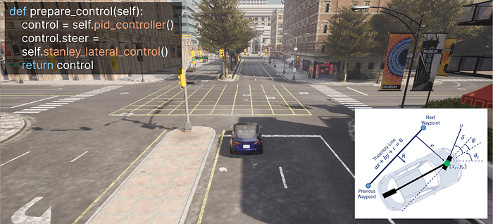
We’ll use a lateral controller (also called a cross-track controller) to calculate the steering angle. It automatically corrects vehicle deviation from the ideal trajectory, using two points:
- Target waypoint: the next waypoint the vehicle aims for.
- Previous waypoint: the waypoint the vehicle passed just before.
An imaginary line connecting these two points represents the ideal path.
Stanley Method
We apply the Stanley algorithm, developed by Stanford’s DARPA Grand Challenge team. It calculates two steering components:
- Heading error: the angular difference between the ideal trajectory direction and the car’s current heading.
- Cross-track error: the lateral offset of the vehicle from the ideal trajectory line.
The sum of these two angles gives the final steering angle, minimizing deviation and guiding the car back to the path.

First, compute the angle difference between the ideal trajectory and the current vehicle heading. The trajectory angle is computed using the coordinates of the current target and previous waypoints:
# Path segment angle
yaw_path = np.arctan2(wp_target[1] - wp_prev[1], wp_target[0] - wp_prev[0])

# Heading error
yaw_diff = yaw_path - vehicle_yaw_rad
Next, find the distance from the vehicle to the ideal path using the equation for the line connecting the previous and target points:
diff_x = target_x - previous_x
diff_y = target_y - previous_y
if diff_x == 0:
 diff_x = 0.1
slope = diff_y / diff_x
correction = previous_y - slope * previous_x

# Equation converted to ax + by + c = 0 form
a = -slope
b = 1.0
c = correction
Calculate the cross-track error (CTE) — the lateral offset from the ideal path:
# Cross-track error calculation
if abs(diff_x) < 1e-6:
 # Vertical line: error based on X
 crosstrack_error = vehicle_location.x - wp_prev[0]
else:
 slope = diff_y / diff_x
 a = -slope
 b = 1.0
 c = (slope * wp_prev[0]) - wp_prev[1]

crosstrack_error = (a * vehicle_location.x + b * vehicle_location.y + c) / np.sqrt(a ** 2 + b ** 2)
Correct the steering angle according to the Stanley method, incorporating lateral error and speed:
yaw_diff_crosstrack = np.arctan(k * crosstrack_error / v)

# Final steering angle
steer_expect = yaw_diff + yaw_diff_crosstrack
We’ll now test a more complex route with turns and curves. The plot displays the planned trajectory (blue) and actual route (red). Launch the test:

Great! Our autonomous vehicle now accurately follows the route, maintaining the correct speed and trajectory.
In short: the Control module translates waypoints into vehicle commands (steer, throttle, brake), using Localization and Planning inputs.
Next, we’ll create an automatic obstacle braking system.
Perception — Object Detection
Code on Github
Launch command: python -m sd_7
So far, our vehicle drives “blindly”: unaware of maps, buildings, roads, or obstacles — knowing only its current position and planned trajectory. If another car or pedestrian appears suddenly, a collision occurs.
To prevent collisions, vehicles use perception systems, relying primarily on three sensors:
- LiDAR: The main sensor, creating a detailed 3D map within ~100 meters. It identifies objects, their shapes, sizes, and distances.
- Radar: Uses radio waves to measure distances, velocities, and trajectories of objects, allowing timely reactions.
- Cameras: Recognize traffic lights, signs, and road markings.
Integrating these sensors and training object detection models is challenging. Carla simulator simplifies this by offering a virtual obstacle sensor combining these functionalities:
obstacle_detected_state = False

obs_bp_library = world.get_blueprint_library()
obs_bp = obs_bp_library.find('sensor.other.obstacle')
obs_bp.set_attribute("distance", "15") # detection distance (meters)
obs_bp.set_attribute("sensor_tick", "0.1") # check frequency (seconds)

obstacle_sensor = world.spawn_actor(obs_bp, sensor_transform, attach_to=vehicle)

# Event handling:
obstacle_sensor.listen(obstacle_callback):
 obstacle_detected_state = True

# Emergency braking on obstacle detection:
if obstacle_detected_state:
 print(" -> Obstacle detected! OVERRIDING control: EMERGENCY BRAKE")
 control.throttle = 0.0
 control.brake = 1.0 # Full brake
Add a car obstacle:
obstacle_bp = world.get_blueprint_library().find('vehicle.audi.tt')
obstacle_bp.set_attribute('role_name', 'obstacle')
obstacle_location = carla.Location(x=10.0, y=24.5, z=0.1)
obstacle_vehicle = world.try_spawn_actor(obstacle_bp, obstacle_transform)
Test the result:
python -m sd_7

Now our car successfully stops before obstacles!
However, what would happen if a pedestrian suddenly steps in front of the car? To avoid such situations, real autonomous vehicles incorporate an additional module called Prediction.
In short: the Perception module detects and identifies objects around the vehicle. It takes sensor data and the current vehicle state (from Localization) as input, outputting detailed information about the recognized objects, such as their type, dimensions, speed, acceleration, and direction of motion.
Prediction — Anticipating Movement of Surrounding Objects
In our virtual world, there currently aren’t any moving objects besides our car. But real-world driving environments are much more complex — other cars, pedestrians, and various obstacles constantly move around the vehicle. To reliably avoid collisions, the autonomous vehicle must anticipate how these objects will behave. Two primary methods are used for this task: the algorithmic approach and machine learning models.
- Algorithmic approach:
Based on the current state of objects, if the vehicle knows the speed and direction of other cars or pedestrians, it can mathematically calculate if their paths will intersect, and thus proactively take measures to prevent a collision. - Machine learning models:
Conversely, machine learning models are trained on vast datasets comprising millions of real-life driving scenarios. Such models are capable of predicting unexpected maneuvers of other road users — for example, sudden braking or unforeseen turns. The effectiveness of this method largely depends on the volume and quality of the training data, as well as the algorithms employed.
Within the scope of this article, we won’t implement our Prediction module, as that would require another two or three extensive articles. If you’re interested, you can explore the Prediction module implemented in the Pylot project (under the prediction section), or try building your predictive model.
In short: Prediction is responsible for anticipating the future behavior of surrounding objects. It receives recognized object data (from Perception) and the current vehicle state (from Localization) as inputs, producing outputs that describe possible trajectories and behaviors of detected objects.
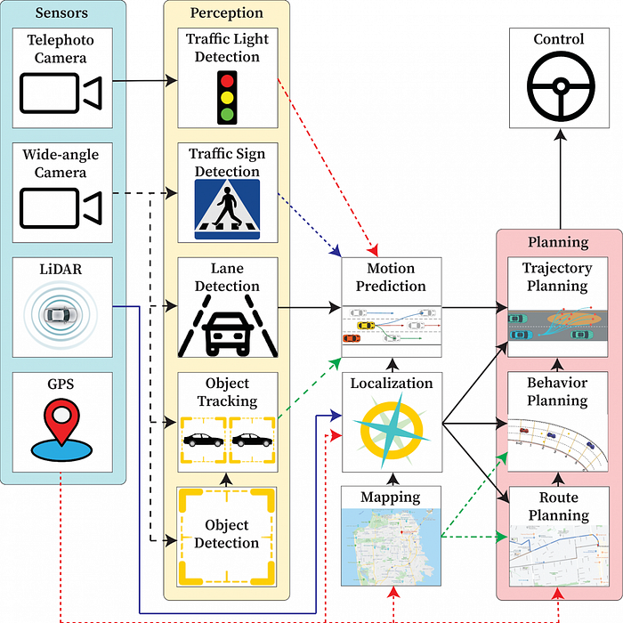
Overall Autonomous Driving System Flowchart

Additional system diagrams of autonomous driving systems:

Conclusion
Our article ends here. If you’d like to dive deeper into the exciting world of self-driving vehicles and autonomous technologies, I recommend relevant courses available on platforms like Coursera or Udacity.
And if one day you encounter an autonomous car on the road, remember — it’s attentively watching you through its sensors (Perception) and attempting to anticipate your actions (Prediction). It always knows precisely where it is (Localization), carefully plans a safe path ahead (Planning), and reliably controls its movement along the route (Control). So don’t be shy — smile and wave! The car’s cameras and LiDAR sensors will definitely notice you!
Join thousands of data leaders on the AI newsletter. Join over 80,000 subscribers and keep up to date with the latest developments in AI. From research to projects and ideas. If you are building an AI startup, an AI-related product, or a service, we invite you to consider becoming a sponsor.
Published via Towards AI
Take our 90+ lesson From Beginner to Advanced LLM Developer Certification: From choosing a project to deploying a working product this is the most comprehensive and practical LLM course out there!
Towards AI has published Building LLMs for Production—our 470+ page guide to mastering LLMs with practical projects and expert insights!

Discover Your Dream AI Career at Towards AI Jobs
Towards AI has built a jobs board tailored specifically to Machine Learning and Data Science Jobs and Skills. Our software searches for live AI jobs each hour, labels and categorises them and makes them easily searchable. Explore over 40,000 live jobs today with Towards AI Jobs!
Note: Content contains the views of the contributing authors and not Towards AI.

