 Logo:
Logo:  Areas Served:
Visual SLAM, A Booster Overview
Last Updated on March 1, 2023 by Editorial Team
Author(s): Mohammad Javadian Farzaneh
Originally published on Towards AI.
Part 1
Purpose of Writing
SLAM is one of the machine vision concepts that is widely used in robotics. My Master’s thesis was related to this concept. It was challenging to understand the concept due to a lack of knowledge about SLAM-related phrases and idioms. So I devoted my time to figuring out the purpose of SLAM and How it works. I decided to write my understanding of SLAM, especially Visual SLAM, to help anyone at the first step without intuition. I hope it will help and ease the process.
Introduction
The “SLAM” is the abbreviation of “Simultaneously Localizing and Mapping.” This algorithm enables a robot to create a map from an unknown environment and simultaneously localize itself to it. There are multiple types and categories of SLAM that utilize various sensors. One of the most used categories is Visual SLAM and Non-Visual SLAM.
Visual SLAM is a type of SLAM that uses the camera as a primary sensor to create maps from captured images. A map is created from a path that the camera has traveled. So in Visual SLAM, we want to recover the camera’s trajectory using images and show it on a 3D/2D map.
Moreover, Visual SLAM itself is divided into three classes based on camera types: Monocular, Stereo, and RGB-D. My research was about Monocular Visual SLAM, so some terms may differ, but the main idea is the same.
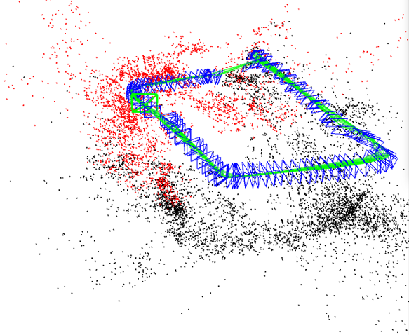 Simple map created from a squared path by ORB-SLAM2
In the above image, a map is created from a sequence of images taken from a squared path. The green line is the trajectory of the camera. Other parts indicate feature points and key-frames which will be discussed in the following parts.
Is there any good reference on the web?
At first, it took much work for me to understand how the Visual SLAM works; tons of papers, articles, and blogs talked about it, but they could have been more beneficial. After a while, I found the book named “Introduction to Visual SLAM From Theory to Practice.” It was a game-changer. I understand most of the concepts and idioms through reading this book. So I will continue my writing from this book.
Framework Of Visual Slam
First, we need a camera sensor to create a visual slam system. The system’s input is images due to using the camera. After capturing the images and doing some per-processing to reduce the noise and enhance the quality, images are ready to be processed for map creation. However, how are images processed? Okay, we will talk about it later. Let us first introduce the framework.
The below image describes the process well:
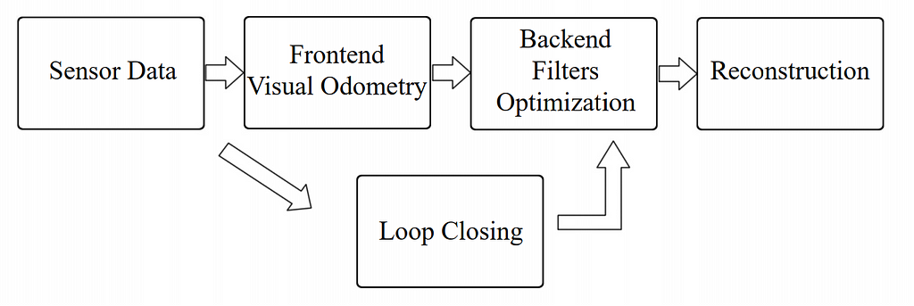 Visual SLAM framework by Xiang Gao and Tao Zhang
We have already discussed sensors and data. Now let us talk about other parts. Most visual slam systems are composed of two major parts: Front-end and Back-end. Front-end is responsible for processing images and extracting points called feature points. The back-end is responsible for optimizing the estimated trajectory and other map parts. There is a part named loop closing. This part checks whether the camera has seen a place again or not, and it is crucial because it will prevent some problems like accumulated drifts from happening. There is a helpful explanation in the link below. Please check it for more info.
Visual Odometry vs. Visual SLAM vs. Structure-from-Motion
What are the features?
As mentioned earlier, the front-end in visual slam extracts feature points. These features make the map, and they are the main components. There are different definitions to answer the question. The simplest one is written on Wikipedia, “a set of information related to computing tasks.” Another superb definition more specific to our discussion is “digital expression of image information.” Based on this term, every image pixel can be considered a feature, but there are some problems with this. The major problem with this approach is that by increasing the size of the image time complexity of the process will be increased, which is not good. Also, SLAM systems need stable features under different image visual changes like rotation, scaling, and brightness. So pixels are not a good candidate. Some other valid features are needed. Research shows that edges and corners in the images can be considered feature points. They have a better application than pixels.
What are edge, corner, and Block?
Edge is part of the image where extreme changes in light brightness are seen in one direction. The intersection of two edges is called a corner. The block is part of the image with no changes or less change in light brightness. The below image shows them visually:
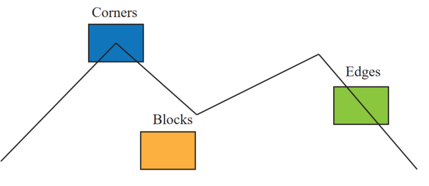 Visual definition of Edge, Corner and Block by Xiang Gao and Tao Zhang
However, again there is a problem with corners and edges. Scaling the image, e.g., making it bigger, a corner may convert to edge or blocks. Please take a look at the image below:
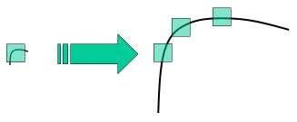 Corner converted to edges due to scaling by opencv.org
In this image, a corner is shown, and then the corner becomes bigger and converted to edges due to scaling. So thanks to this problem again we need more reliable feature points. Some algorithms extract more valuable and reliable features, such as SIFT, SURF, and ORB. Nowadays, ORB is used more than other algorithms due to its speed and robustness. There is a helpful explanation about ORB in the link below.
Introduction to ORB (Oriented FAST and Rotated BRIEF)
How to find camera trajectory using feature points?
After extracting features, image matching is the most basic yet important thing to do. Image matching helps us at first to know that the images are related enough to use them in the slam algorithm. Finding corresponding matched feature points that help us to estimate the camera pose (Rotation + Translation) is the second usage of them.
To show a camera or any point in the map (if the 3D map is used), three entities: X, Y, and Z, are needed. In monocular slam, since the depth of the images is not accessible, and the only thing we have is 2D images, the recovery of the three mentioned entities is hard and almost impossible. So some estimation should be done. We call it “Initialization.” Initialization is a crucial step in monocular slam because depth, scale, and the very first pose of the camera will be found. The calculations in this step are done based on epipolar geometry by extracting essential or fundamental matrices. Long story short, essential or fundamental matrices are needed to get the first pose of the camera. They can be extracted from an equation named epipolar constraint equal to zero.
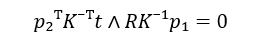 epipolar constraint equation
In the above equation, p1 and p2 are two matched feature points showing an identical 3D position of a point in real-world coordinates. K is an intrinsic matrix composed of focal length and principal point. This matrix can be found using camera calibration methods. t is a vector showing the translation.
We can form the Essential matrix by extracting ? ∧ ?. If we need the fundamental matrix, we use this formula ? = ?⁻ᵀ ? ? ⁻¹ where E is an essential matrix. Now we can use Singular Value Decomposition(SVD) to find the camera pose equal to the projection matrix or camera pose.
How to estimate the feature points real position?
Now that we have the projection matrix, we can estimate the 3D position of feature points using the “ Triangulation” method. Extracted feature points are all in the image coordinate system. At first, we bring them to the normalized plane (If you are unfamiliar with the normalized plane, it is better to read about the pinhole camera model). When these points are in the normalized plane, we can use their x and y coordinates as the 3D x and y, so the only remaining item will be z because, as mentioned earlier, in monocular cameras, depth is missing.
To calculate the z consider the image below,
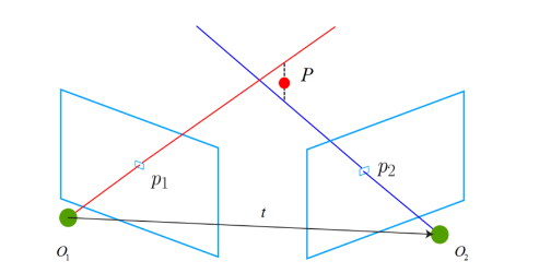 Triangulation explanation.
In this image, P1 and P2 are feature points pointing to an identical 3D point P located in the real world. Two blue rectangles are the images that P1 and P2 were extracted from receptively. Since these two points indicate the same real-world point and are identical, changing the P1 coordinate system to the P2 coordinate system P1 should fall precisely on P2 (Based on pinhole camera models and equations). So to change the P1 camera coordinate, we need an extrinsic matrix, the camera pose, or the projection matrix found in the previous part.
To compute the z parameter below formula is used:
Z₂ X₂ = [?₂₁ ?₂₁] Z₁ X₁
In the above formula, X parameters are P1 and P2 coordinates in the normal plane, calculated by multiplying P1 and P2 into the inverse of the intrinsic matrix (K).
Based on the above formula, the X1 point will shift to the coordinate system of the X2 point. Our goal is to find Z parameters so that the distance of two points in one coordinate system becomes as minimum as possible.
Up to now, we have discussed how to find and estimate the very first elements of a map. After initialization, we can use the PnP algorithm to estimate the new frames’ camera pose and its new feature points.
This article has become long and may become dull, and I will explain the remaining parts in the following articles.
Reference:
Gao, X. and Zhang, T., 2021. Introduction to visual SLAM: from theory to practice. Springer Nature.
Visual SLAM, A Booster Overview was originally published in Towards AI on Medium, where people are continuing the conversation by highlighting and responding to this story.
Join thousands of data leaders on the AI newsletter. Join over 80,000 subscribers and keep up to date with the latest developments in AI. From research to projects and ideas. If you are building an AI startup, an AI-related product, or a service, we invite you to consider becoming a sponsor.
Published via Towards AI
Related posts

Popular posts

 for 2021")


Updates

Recent Posts